The first stage of the
variable frequency AC drive is the frequency converter. The converter consists of six diodes, similar to the check valves used in plumbing systems. They allow current to flow in only one direction: the direction indicated by the arrow in the diode symbol. For example, whenever phase A voltage (voltage similar to pressure in plumbing) is more positive than phase B or C voltage, then the diode will open and allow current to flow. When phase B becomes more positive than phase A, the phase B diode will open and the phase A diode will close. The same goes for the 3 diodes on the negative side of the bus. So we get six pulses of current as each diode turns on and off. This is called a six-pulse VFD, and it's standard on current frequency converters.
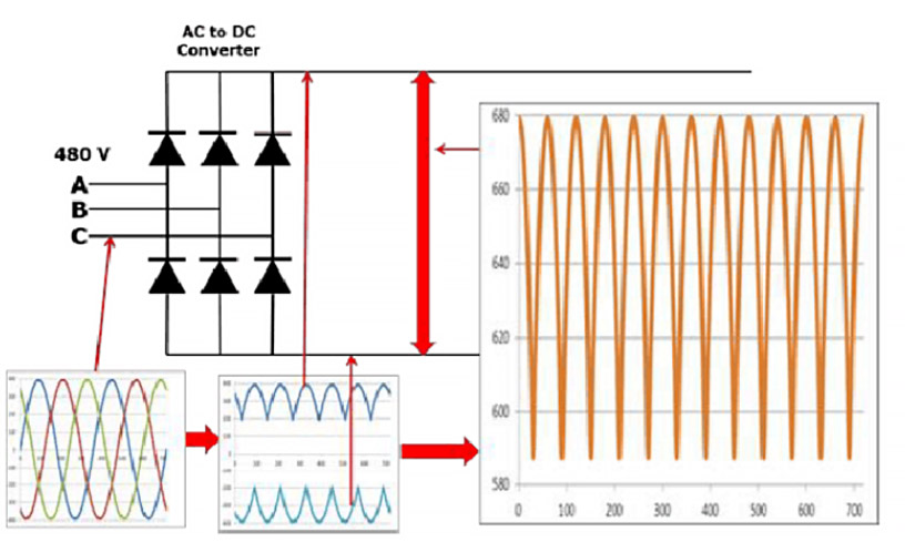
We can remove the AC ripple on the DC bus by adding a capacitor. Capacitors operate in a similar manner to reservoirs or accumulators in piping systems. This capacitor absorbs the AC ripple and provides a smooth DC voltage. The AC ripple on the DC bus is typically less than 3 volts. Therefore, the voltage on the DC bus becomes about 650VDC. The actual voltage depends on the voltage level fed into the AC line by the variable frequency drive, the level of voltage unbalance on the power system, the motor load, the power system impedance and any reactors or harmonic filters on the frequency converter.
A diode bridge converter that converts AC to DC is sometimes just called a converter. A converter that converts DC back to AC is also a converter, but to distinguish it from a diode converter it is often called an inverter. In industry it has become common to refer to any DC-AC converter as an inverter.
When we close one of the top switches in the inverter, the phase of the motor is connected to the positive DC bus and the voltage on that phase becomes positive. When we close one of the bottom switches in the converter, that phase is connected to the negative DC bus and goes negative. We can therefore make any phase of the motor positive or negative at will, and thus produce any frequency we want. So, we can make any stage positive, negative or zero.
The output of the VFD is a rectangular waveform. VFDs do not produce a sinusoidal output. This rectangular waveform is not a good choice for a general power distribution system, but is perfectly adequate for an electric motor.
If we wanted to reduce the motor frequency to 30 Hz, then we would simply switch the inverter output transistors more slowly. However, if we reduce the frequency to 30Hz, then we must also reduce the voltage to 240V to maintain the V/Hz ratio.
This is called pulse width modulation or PWM. Imagine we could control the pressure in water pipes by switching valves on and off at high speed. While this isn't very practical for piping systems, it works well for VFDs. Note that in the first half cycle, the voltage is ON half the time and OFF half the time. So the average voltage is half of 480V or 240V. With the pulse output we can get any average voltage at the output of the VFD.


 IPv6 network supported


 English
 فارسی
فارسی français
 русский
 español
 português
 العربية
 Türkçe
 ไทย
ไทย Tiếng Việt